
The inclination of parents to buy cell phones for their children and teenagers is understandable. Th
Se næste indlæg >
Learn how to construct a cell phone signal jammer through this DIY project
perfectjammer
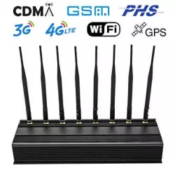
A cell phone jammer is an electronic device that blocks signal transmission between a cell phone and a cell tower. By using the same frequencies as cell phones, signal jammers can cause strong interference with communications between callers and receivers. Can effectively block signal transmission from networks such as UMTS, 3G, CDMA, GSM and PHS.
DIY Cell Phone Jammer – Components Required
| COMPONENT | COMPONENTUSAGE |
| Resistor R1 | Emitter Loading |
| Resistor R2 | Base Biasing |
| Capacitor C1 | Frequency Generation |
| Capacitor C2 | Feedback |
| Capacitor C3 | Feedback |
| Capacitor C4 | Noise Reduction |
| Capacitor C5 | Coupling |
| Capacitor C6 | Coupling |
| Capacitor C7 | Decoupling |
| Transistor Q1 | Amplification |
| Inductor L1 | Frequency Generation |
For any jammer circuit, there must be three important sub-circuits:
- RF amplifier
- Voltage Controlled Oscillator
- Tuning circuit
These 3 circuits combine to form an efficient cell phone jammer circuit.
Cell phone signal jammer working
Transistor Q1, along with capacitors C4 and C5, and resistor R1, is part of the RF amplifier circuit. This circuit’s purpose is to amplify the signal generated by the tuned circuit. The amplified signal is subsequently transmitted to the antenna through capacitor C6, which serves to block DC current and exclusively allow the transmission of the AC component of the signal.
When transistor Q1 is in the on state, the tuned circuit connected to the collector is also in the on state. This circuit, comprising of capacitor C1 and inductor L1, functions as a zero resistance oscillator, resulting in the production of very high frequencies with minimal damping.
Over time, the magnetic charge passing through the inductor decreases, causing the capacitor to accumulate charge in the opposite or reverse polarity. This cycle is repeated, and eventually, the inductor charges the capacitor until it reaches a state of zero charge.
Oscillation ceases once internal resistance is formed, marking the ongoing nature of this process. Prior to reaching the collector terminal, the RF amplifier feed passes through capacitor C5, then C6. Capacitors C2 and C3 generate random pulses (noise) at the frequency generated by the tuned circuit.
RF amplifiers play a crucial role in amplifying the frequencies generated by tuned circuits. These amplifiers combine and amplify the frequency produced by the tuned circuit along with the noise signal generated by capacitors C2 and C3, before transmitting it.

Ingen kommentarer endnu